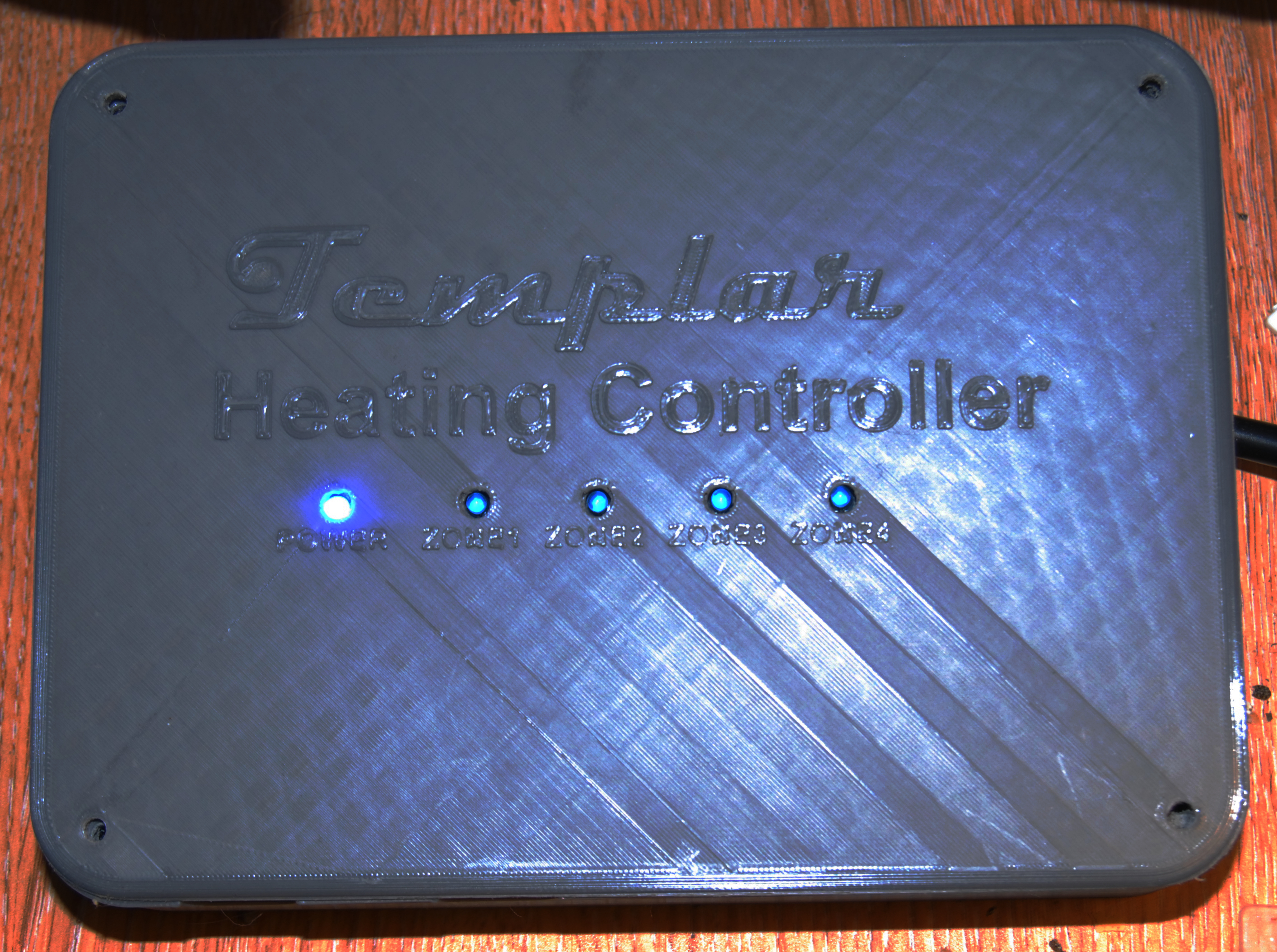
the unit now has a nice 3D printed case http://vps.templar.co.uk/Odds%20and%20Ends/BCD_0026.JPG
The Natural Philosopher wrote:
the unit now has a nice 3D printed case
http://vps.templar.co.uk/Odds%20and%20Ends/BCD_0026.JPG
If your friend can enable monotonic infill, it would avoid those
diagonal stripes where it navigates around the LED holes ...
Pi connectors. I bought kit to make up Pi female connectors to go from
the pins on one board to pins on another. I wasted a whole day and a
half and was completely unable to make a satisfactory lead up , either
by crimping or by soldering.
Gave up and bought jumper leads.
All earths are not created equal. I wanted to use a 5 way connector to
pins 31,33,35,37 with pin 39 as power and signal earth on the Pi Zero W.
I don't know what pin 39 is connected to, but it sure ain't earth. maybe
via a high resistance, but not enough to power a Pi. I used pin 6, and
that worked...
And to think I used to do this for a living...
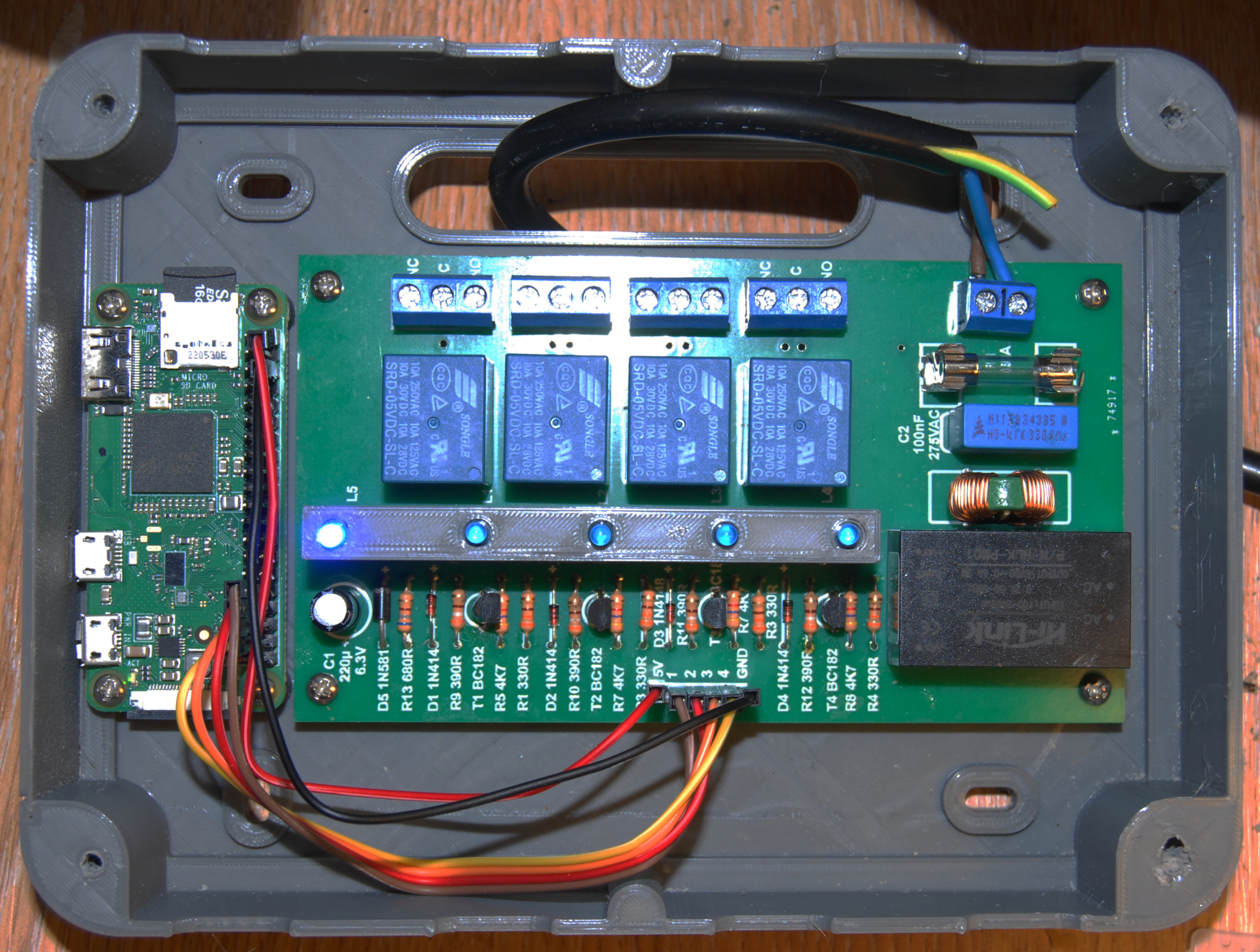
My Pi ZERO W heating controller is alive, but it took some forceps...
First Problem:
Not all transistors are created equal. I used obsolete transistors that
I used to use years ago - BC182... but they didn't work. Turns out
today's BC182 has a different pinout from what I was used to - *BC182L*
was the solution. That worked.
Second Problem:
Pi connectors. I bought kit to make up Pi female connectors to go from
the pins on one board to pins on another. I wasted a whole day and a
half and was completely unable to make a satisfactory lead up , either
by crimping or by soldering.
Gave up and bought jumper leads.
Third problem:
All earths are not created equal. I wanted to use a 5 way connector to
pins 31,33,35,37 with pin 39 as power and signal earth on the Pi Zero W.
I don't know what pin 39 is connected to, but it sure ain't earth. maybe
via a high resistance, but not enough to power a Pi. I used pin 6, and
that worked...
There are still some software issues to resolve, but the unit now has a
nice 3D printed case and the relays all click and the LEDs all light...
*phew*.
http://vps.templar.co.uk/Odds%20and%20Ends/BCD_0027.JPG http://vps.templar.co.uk/Odds%20and%20Ends/BCD_0026.JPG
I bought kit to make up Pi female connectors to go from the pins on one
board to pins on another. I wasted a whole day and a half and was completely unable to make a satisfactory lead up , either by crimping
or by soldering.
Gave up and bought jumper leads.
On 10/25/23 8:57 AM, The Natural Philosopher wrote:
And to think I used to do this for a living...
My Pi ZERO W heating controller is alive, but it took some forceps...
First Problem:
Not all transistors are created equal. I used obsolete transistors
that I used to use years ago - BC182... but they didn't work. Turns
out today's BC182 has a different pinout from what I was used to -
*BC182L* was the solution. That worked.
IF possible, stick to super-popular "legacy" transistors.
2n2222 are very versatile, 3809s are ok if you don't need
to handle much power.
There are some 'logic level' MOSFET-family out there that
are very good for higher power levels. Again, stick to the
classics if possible.
Second Problem:
Pi connectors. I bought kit to make up Pi female connectors to go from
the pins on one board to pins on another. I wasted a whole day and a
half and was completely unable to make a satisfactory lead up ,
either by crimping or by soldering.
Gave up and bought jumper leads.
'Connections' ALWAYS seem to be an unnecessary bitch.
Third problem:
All earths are not created equal. I wanted to use a 5 way connector to
pins 31,33,35,37 with pin 39 as power and signal earth on the Pi Zero W.
Heh, heh ... yep, 'earths' are NOT all created equal.
Look into RS-4xx data connections for fun ... some
'earths' can cause HUGE DEADLY current flow :-)u
Clue, two "ground" connections even 500-1000 feet
apart are NOT gonna be at the same potential. Oft
wondered if you can get actual usable power from
that ...... can 0.25 volts dif, at a potential
100-1000 amps, be converted to higher voltage/
lower amps these days ?
I don't know what pin 39 is connected to, but it sure ain't earth.
maybe via a high resistance, but not enough to power a Pi. I used pin
6, and that worked...
The 7th pin, on the top edge, is a fairly reliable ground.
Be cautious otherwise unless it's something stupid like
powering a fan.
There are still some software issues to resolve, but the unit now has
a nice 3D printed case and the relays all click and the LEDs all light...
*phew*.
http://vps.templar.co.uk/Odds%20and%20Ends/BCD_0027.JPG
http://vps.templar.co.uk/Odds%20and%20Ends/BCD_0026.JPG
I'm slowly putting together a home-security system
with all the goodies - including opto-isolated
inputs. It is gonna run on a Pi4 or now maybe on
a Pi5, sporting a usable web interface. Switches,
detectors, video ... all in one.
The Natural Philosopher wrote:
I bought kit to make up Pi female connectors to go from the pins on
one board to pins on another. I wasted a whole day and a half and was
completely unable to make a satisfactory lead up , either by crimping
or by soldering.
Gave up and bought jumper leads.
Don't think I'd trust a bunch of DuPont wires long term ... at least hot
snot them in place.
The Natural Philosopher <tnp@invalid.invalid> wrote:
Pi connectors. I bought kit to make up Pi female connectors to go from
the pins on one board to pins on another. I wasted a whole day and a
half and was completely unable to make a satisfactory lead up , either
by crimping or by soldering. Gave up and bought jumper leads.
If they were ribbon cable connectors then I can understand that - you
really want the proper tool for pushing those together when they're that wide.
In message <65398740@news.ausics.net>
not@telling.you.invalid (Computer Nerd Kev) wrote:
The Natural Philosopher <tnp@invalid.invalid> wrote:
Pi connectors. I bought kit to make up Pi female connectors to go
from the pins on one board to pins on another. I wasted a whole day
and a half and was completely unable to make a satisfactory lead up
, either by crimping or by soldering. Gave up and bought jumper
leads.
If they were ribbon cable connectors then I can understand that - you
really want the proper tool for pushing those together when they're
that wide.
I've found it not too difficult to do ribbon insulation displacement
cables if you have a vice, but the caveats I can think of are:
Use a VERY sharp pair of scissors to cut the cable. If it isn't cut
cleanly, there may be little bits of copper core hanging out, just
waiting to short to a neighbour. (Been there.)
Connectors need to be crunched on at very close to 90 degrees to the
cable. It's surprising how little margin for error there is, or else
there may be shorts between adjacent cores.
The vice's jaws need to cover the whole connector and to close parallel.
If the jaw surfaces are serrated, some dense cardboard may help, but you
will need them held in place simply to avoid having to keep so many bits
all in the right place as you tighten the vice.
I will shortly be getting my own printer. I would appreciate any tips
like these you can give me!
On 25/10/2023 14:49, Andy Burns wrote:
The Natural Philosopher wrote:
the unit now has a nice 3D printed case
http://vps.templar.co.uk/Odds%20and%20Ends/BCD_0026.JPG
If your friend can enable monotonic infill, it would avoid those
diagonal stripes where it navigates around the LED holes ...
I will shortly be getting my own printer. I would appreciate any tips
like these you can give me!
On 26/10/2023 05:27, 56d.1152 wrote:
On 10/25/23 8:57 AM, The Natural Philosopher wrote:Good project.
And to think I used to do this for a living...
My Pi ZERO W heating controller is alive, but it took some forceps...
First Problem:
Not all transistors are created equal. I used obsolete transistors
that I used to use years ago - BC182... but they didn't work. Turns
out today's BC182 has a different pinout from what I was used to -
*BC182L* was the solution. That worked.
IF possible, stick to super-popular "legacy" transistors.
2n2222 are very versatile, 3809s are ok if you don't need
to handle much power.
There are some 'logic level' MOSFET-family out there that
are very good for higher power levels. Again, stick to the
classics if possible.
Second Problem:
Pi connectors. I bought kit to make up Pi female connectors to go
from the pins on one board to pins on another. I wasted a whole day
and a half and was completely unable to make a satisfactory lead up
, either by crimping or by soldering.
Gave up and bought jumper leads.
'Connections' ALWAYS seem to be an unnecessary bitch.
Third problem:
All earths are not created equal. I wanted to use a 5 way connector
to pins 31,33,35,37 with pin 39 as power and signal earth on the Pi
Zero W.
Heh, heh ... yep, 'earths' are NOT all created equal.
Look into RS-4xx data connections for fun ... some
'earths' can cause HUGE DEADLY current flow :-)u
Clue, two "ground" connections even 500-1000 feet
apart are NOT gonna be at the same potential. Oft
wondered if you can get actual usable power from
that ...... can 0.25 volts dif, at a potential
100-1000 amps, be converted to higher voltage/
lower amps these days ?
I don't know what pin 39 is connected to, but it sure ain't earth.
maybe via a high resistance, but not enough to power a Pi. I used pin
6, and that worked...
The 7th pin, on the top edge, is a fairly reliable ground.
Be cautious otherwise unless it's something stupid like
powering a fan.
There are still some software issues to resolve, but the unit now has
a nice 3D printed case and the relays all click and the LEDs all
light...
*phew*.
http://vps.templar.co.uk/Odds%20and%20Ends/BCD_0027.JPG
http://vps.templar.co.uk/Odds%20and%20Ends/BCD_0026.JPG
I'm slowly putting together a home-security system
with all the goodies - including opto-isolated
inputs. It is gonna run on a Pi4 or now maybe on
a Pi5, sporting a usable web interface. Switches,
detectors, video ... all in one.
I have all the wiring here for a home security system but I never
installed one because I retired at that point and the house was never empty
On 26/10/2023 08:30, Andy Burns wrote:
The Natural Philosopher wrote:
I bought kit to make up Pi female connectors to go from the pins on
one board to pins on another. I wasted a whole day and a half and
was completely unable to make a satisfactory lead up , either by
crimping or by soldering.
Gave up and bought jumper leads.
Don't think I'd trust a bunch of DuPont wires long term ... at least
hot snot them in place.
Used 100% to connect model plane servos. They are pretty good. That
units going to be screwed onto a wall and never moved again.
I might add a zip tie or two.
I wouldn't trust it in a car though - there I would follow your advice
Solder IS the best.
But, remember "wire wrap" ?
Still have the tools
for doing that. The more-extensive wrapping CAN
be as reliable as soldered connections.
But, remember "wire wrap" ? Still have the tools
for doing that. The more-extensive wrapping CAN
be as reliable as soldered connections.
I was told, back in the day, that it's more reliable. Many mainframes
had wire-wrapped backplanes. I recall seeing engineers come in during maintenance time to replace wires due to upgrades or bug fixes; their
being wire-wrapped made it rather easier.
But, remember "wire wrap" ?
I was trained, as an apprentice, on military spec hardware construction:
Wire wrap was one system that was used extensively in early digital
hardware backplane prototyping.
Once the design was stabilised they tended to replace all that with a 2
layer PCB.
Still have the tools for doing that. The more-extensive wrapping CAN
be as reliable as soldered connections.
Yes. especially in high vibration environments where components are not mechanically connected except by their leads or pins.
On Thu, 26 Oct 2023 16:16:33 +0100, David Higton wrote:
In message <65398740@news.ausics.net>
not@telling.you.invalid (Computer Nerd Kev) wrote:
The Natural Philosopher <tnp@invalid.invalid> wrote:
Pi connectors. I bought kit to make up Pi female connectors to go
from the pins on one board to pins on another. I wasted a whole day
and a half and was completely unable to make a satisfactory lead up
, either by crimping or by soldering. Gave up and bought jumper
leads.
If they were ribbon cable connectors then I can understand that - you really want the proper tool for pushing those together when they're
that wide.
I've found it not too difficult to do ribbon insulation displacement
cables if you have a vice, but the caveats I can think of are:
Use a VERY sharp pair of scissors to cut the cable. If it isn't cut cleanly, there may be little bits of copper core hanging out, just
waiting to short to a neighbour. (Been there.)
Connectors need to be crunched on at very close to 90 degrees to the
cable. It's surprising how little margin for error there is, or else
there may be shorts between adjacent cores.
The vice's jaws need to cover the whole connector and to close parallel.
If the jaw surfaces are serrated, some dense cardboard may help, but you will need them held in place simply to avoid having to keep so many bits all in the right place as you tighten the vice.
Curiosity: would it help to use one of the spray-on contact cements or one
of the cyanoacrylates (e.g. Zap) to hold things in place while they're in
the vice?
I will shortly be getting my own printer. I would appreciate any tips
like these you can give me!
On 25/10/2023 3:51 pm, The Natural Philosopher wrote:
I use octoprint (octoprint.org) on a Pi 2 I had lying about.
I will shortly be getting my own printer. I would appreciate any tips
like these you can give me!
To design items I use tinkercad.com. If you already know about CAD use whatever you're familiar with. I was 77 when I started and this was
adequate.
Pass the designed object (.stl file) to prusa slicer:
https://github.com/prusa3d/PrusaSlicer/releases
and then to octopi.
Adhesion of the object to the print bed is THE major problem, too lttle adhesion and the print WILL at some stage float off the bed, too much adhesion and it will be impossible to remove from the surface. I use a magnetic layer, you remove it from the bed and bend it to remove the print.
The instructions will say use a sheet of paper to set the nozzle height.
Use a 0.30mm feeler gauge.
If you intend to print gears or pulleys come back to me.
If you're prone to frustration take a tranquiliser before you start.
Good luck
Another Dave
On 27/10/2023 04:44, 56d.1152 wrote:
No, actually it often isn't...
Solder IS the best.
The problem with solder on *stranded* wire is that it wicks up the wire
and reduces it's flexibility by binding the strands together: That
creates a stress concentration where it stops and a likely cause of
fracture failure under vibration. That is why crimps are the choice for cheaper connections in high stress environments (e.g. automotive) or if
you must solder you absolutely need to mechanically support the wire
upstream of the solder joint.
But, remember "wire wrap" ?
I was trained, as an apprentice, on military spec hardware construction:
Wire wrap was one system that was used extensively in early digital
hardware backplane prototyping.
Once the design was stabilised they tended to replace all that with a 2
layer PCB.
Still have the tools
for doing that. The more-extensive wrapping CAN
be as reliable as soldered connections.
Yes. especially in high vibration environments where components are not mechanically connected except by their leads or pins.
Most 'computer' people these days are really most entirely
'software'. They can't see mechanical or noise or RF issues that crop
up in the Real World. The 'techs' who DO may not be as good with
software. It's a problem. There's a window of maybe 1960 to 1985
where 'programming' and 'design/construction' kinda went together.
Not nearly as many now who cover one end to the other except maybe
the "BattleBots" crowd.
On 10/27/23 12:32 AM, The Natural Philosopher wrote:
On 27/10/2023 04:44, 56d.1152 wrote:
Solder IS the best.
No, actually it often isn't...
The problem with solder on *stranded* wire is that it wicks up the wire
and reduces it's flexibility by binding the strands together: That
creates a stress concentration where it stops and a likely cause of fracture failure under vibration. That is why crimps are the choice for cheaper connections in high stress environments (e.g. automotive) or if
you must solder you absolutely need to mechanically support the wire upstream of the solder joint.
I've had very bad luck with 'crimps' - esp when they are
exposed to the weather, but even in higher-vibration
environments. Wasted lots of time trying to track down
problems related to crimps.
On Fri, 27 Oct 2023 21:57:07 -0400, 56d.1152 wrote:
Most 'computer' people these days are really most entirelyNo argument here (my background is systems design and programing on Mainframes, minicomputers and fault-tolerant systems.
'software'. They can't see mechanical or noise or RF issues that crop
up in the Real World. The 'techs' who DO may not be as good with
software. It's a problem. There's a window of maybe 1960 to 1985
where 'programming' and 'design/construction' kinda went together.
Not nearly as many now who cover one end to the other except maybe
the "BattleBots" crowd.
The other gang that understand interactions between electronics and
vibration are model flyers: radio control models, drones and, the most vibration of all, IC powered free flight competition models: a current F1C class model has a 2.5cc engine putting out around 1.3 HP at 30,000 rpm and carrying electronic flight timers and a GPS-based radio beacon as a
retrieval aid. Free flight models regularly travel 2km or so in the course
of a 3 minute flight, especially if the contest is being run on
Sculthorpe, an ex-RAF/USAF base in Norfolk,UK. This area is known for its fresh sea breezes.
On Thu, 26 Oct 2023 23:44:48 -0400
"56d.1152" <56d.1152@ztq9.net> wrote:
But, remember "wire wrap" ? Still have the tools
for doing that. The more-extensive wrapping CAN
be as reliable as soldered connections.
A good wire wrap connection (done with a power tool - we always
used Gardner-Denver) is gas tight and extremely reliable as well as being faster and easier to modify than soldering.
In message <BuudnQ1ot_sf96H4nZ2dnZfqn_GdnZ2d@earthlink.com>
"56d.1152" <56d.1152@ztq9.net> wrote:
On 10/27/23 12:32 AM, The Natural Philosopher wrote:
On 27/10/2023 04:44, 56d.1152 wrote:
No, actually it often isn't...
Solder IS the best.
The problem with solder on *stranded* wire is that it wicks up the wire
and reduces it's flexibility by binding the strands together: That
creates a stress concentration where it stops and a likely cause of
fracture failure under vibration. That is why crimps are the choice for
cheaper connections in high stress environments (e.g. automotive) or if
you must solder you absolutely need to mechanically support the wire
upstream of the solder joint.
I've had very bad luck with 'crimps' - esp when they are
exposed to the weather, but even in higher-vibration
environments. Wasted lots of time trying to track down
problems related to crimps.
I still remember a very interesting one in the 1980s with a joystick
for a Sinclair Spectrum.
The box proudly proclaimed the use of gold
plating in the internal connections. They used fully (i.e. not
selectively) gold plated crimps onto stranded tinned copper wire.
One of the joints, although completely mechanically sound, was not
conducting electricity. Yes, that really was the interface between
the crimp and the wire.
I ran solder in and it was fine.
There is a known, but unfortunately not widely known, problem in the interface between gold and tin.
The lesson boils down to:
1) Never mix gold plated and tin plated connectors.
2) If you're using gold plated connectors, use selectively gold plated
crimps in them.
The other gang that understand interactions between electronics and
vibration are model flyers: radio control models, drones and, the most
vibration of all, IC powered free flight competition models: a current
F1C class model has a 2.5cc engine putting out around 1.3 HP at 30,000
rpm and carrying electronic flight timers and a GPS-based radio beacon
as a retrieval aid. Free flight models regularly travel 2km or so in
the course of a 3 minute flight, especially if the contest is being run
on Sculthorpe, an ex-RAF/USAF base in Norfolk,UK. This area is known
for its fresh sea breezes.
An actual hydrocarbon-fuel engine WILL create a lot of very buzzy
vibration - which WILL take its toll on every connection. It's
amazing how quickly some connections will fail - chips can even work
their way out of conventional sockets.
And then, if an ignition system is involved, transient electrical
noise ! :-)
On Mon, 30 Oct 2023 00:51:14 -0400, 56d.1152 wrote:
High performance model engines have no ignition: they're either diesels (COMPRESSION IGNITION burning an oil/kerosene/ether mix) or gloplugThe other gang that understand interactions between electronics and
vibration are model flyers: radio control models, drones and, the most
vibration of all, IC powered free flight competition models: a current
F1C class model has a 2.5cc engine putting out around 1.3 HP at 30,000
rpm and carrying electronic flight timers and a GPS-based radio beacon
as a retrieval aid. Free flight models regularly travel 2km or so in
the course of a 3 minute flight, especially if the contest is being run
on Sculthorpe, an ex-RAF/USAF base in Norfolk,UK. This area is known
for its fresh sea breezes.
An actual hydrocarbon-fuel engine WILL create a lot of very buzzy
vibration - which WILL take its toll on every connection. It's
amazing how quickly some connections will fail - chips can even work
their way out of conventional sockets.
And then, if an ignition system is involved, transient electrical
noise ! :-)
ignition (battery heated plug with platinum coil to start, when running combustion keeps the plug hot and burning methanol/oil mix, sometimes with added nitromethane for more power.
You quickly learn how to protect in-model electronics and associated
wiring from the engine's vibration - if you don't you'll have lots of more
or less spectacular crashes. An F1C class model can climb vertically to around 120m with a 3 second engine run.
Recently replaced a plug socket. Put SOLDER over the
ends of the wires and used the SCREW DOWN terminals
rather than the "push in" ones. A little extra effort
PAYS OFF longer term.
On 05/11/2023 04:33, 56d.1152 wrote:
Recently replaced a plug socket. Put SOLDER over the
ends of the wires and used the SCREW DOWN terminals
rather than the "push in" ones. A little extra effort
PAYS OFF longer term.
But best practice documents say using soldered/tinned wire in screw connectors is bad due to differing expansion rates of the brass fitting
and solder. With enough sufficient thermal cycles the connection loosens causing bad connections.
Obviously the experts should have consulted with you.
Recently replaced a plug socket. Put SOLDER over the
ends of the wires and used the SCREW DOWN terminals
rather than the "push in" ones. A little extra effort
PAYS OFF longer term.
In message <UQ92N.38940$sqIa.2684@fx07.iad>
scott@alfter.diespammersdie.us wrote:
56d.1152 <56d.1152@ztq9.net> wrote:
Recently replaced a plug socket. Put SOLDER over the
ends of the wires and used the SCREW DOWN terminals
rather than the "push in" ones. A little extra effort
PAYS OFF longer term.
Sounds like a recipe for a fire. I've seen screw terminals on 3D-printer
motherboards that were scorched after tinned wires had been put in them,
and they only carried maybe 100-200W at 12-24V.
Never ever use screw terminals onto stranded wire that you've tinned.
Solder suffers from creep, so the pressure slowly relaxes until the
joint is loose. As stated above, a recipe for a fire.
| Sysop: | Xerxes |
|---|---|
| Location: | Azle, Texas |
| Users: | 119 |
| Nodes: | 10 (0 / 10) |
| Uptime: | 156:51:26 |
| Calls: | 3,036 |
| Calls today: | 4 |
| Files: | 156 |
| U/L today: |
0 files (0K bytes) |
| D/L today: |
0 files (0K bytes) |
| Messages: | 294,066 |
| Posted today: | 0 |