The dear chinese sent me 10 PCBs instead of one, so if anyone UK want a
PCB to build a mains powered power supply with 4 x 250VAC capable relays buffered to suit raspberry PI GPIO current levels....
Let me know. Correct power supply choice would make it OK for 110V
The Natural Philosopher <tnp@invalid.invalid> wrote:
The dear chinese sent me 10 PCBs instead of one, so if anyone UK want a
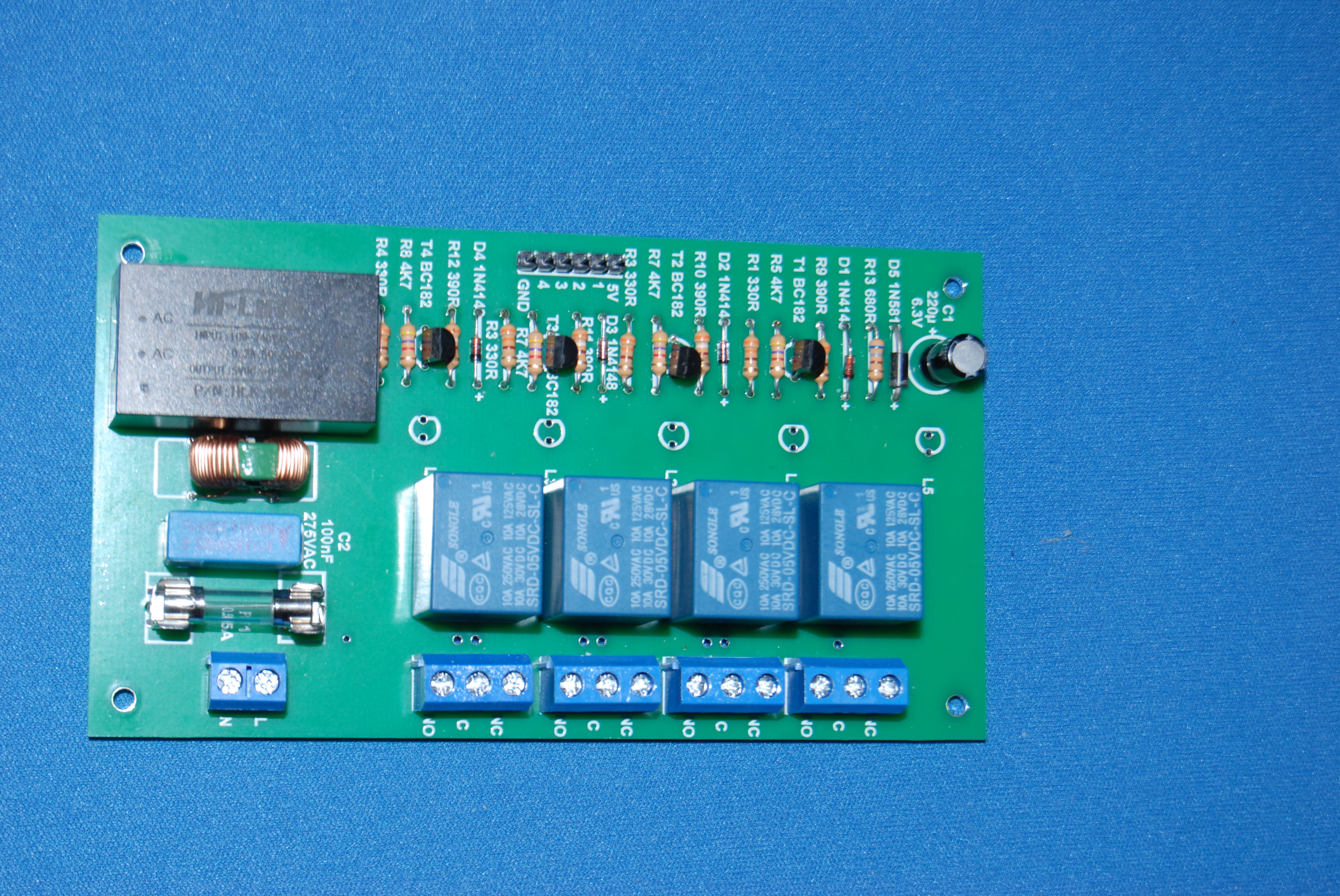
PCB to build a mains powered power supply with 4 x 250VAC capable relays
buffered to suit raspberry PI GPIO current levels....
That's a nice board - clear markings, easy to access components, neat power supply. What tool did you use to design it, out of interest?
Let me know. Correct power supply choice would make it OK for 110V
I made my own similar board last year - 7 relays, in a much tighter space, mains coils and contacts (but still trying to keep the best isolation I could).
I now need to trigger one mains coil from a Pi without exporting mains or putting any DC wiring in the all-mains enclosure (where I can't get good isolation). Current plan is to make a photo-triac triggered by light from
an LED on the Pi carried on some optical fibre...
Theo
I assumed it was a standard board. A 5v/240v relay is a common
requirement. I used a very similar board, before I switched to using Shelly/Sonoff type devices. It even had 4 relays, when I only wanted one.
The Natural Philosopher <tnp@invalid.invalid> wrote:Since when I did this professionally it was black tape on clear film, I
The dear chinese sent me 10 PCBs instead of one, so if anyone UK want a
PCB to build a mains powered power supply with 4 x 250VAC capable relays
buffered to suit raspberry PI GPIO current levels....
That's a nice board - clear markings, easy to access components, neat power supply. What tool did you use to design it, out of interest?
Let me know. Correct power supply choice would make it OK for 110V
I made my own similar board last year - 7 relays, in a much tighter space, mains coils and contacts (but still trying to keep the best isolation I could).
I now need to trigger one mains coil from a Pi without exporting mains or putting any DC wiring in the all-mains enclosure (where I can't get good isolation). Current plan is to make a photo-triac triggered by light from
an LED on the Pi carried on some optical fibre...
Theo
Pancho <Pancho.Jones@proton.me> wrote:
I assumed it was a standard board. A 5v/240v relay is a common
requirement. I used a very similar board, before I switched to using
Shelly/Sonoff type devices. It even had 4 relays, when I only wanted one.
Chinese relay boards aren't uncommon, eg: https://www.ebay.co.uk/itm/262499095094
- on that one there are optocouplers between the inputs and the relay coils, for some reason (maybe they were cheaper than transistors, or they really don't trust the relays' isolation?)
The nice thing about TNP's board is there's a mains to 5V converter on
board, which means you can power the board from the mains that you're switching. Otherwise you need to arrange for a separate DC power supply,
and that gets annoying in a tight space - with this board you don't need a separate power supply for the Pi.
Theo
Since when I did this professionally it was black tape on clear film, I
ended up using Corel Draw! I started with a 3D modelling program to make
sure the physical bits fitted, then exported the copper to Corel,
because I am very fluent in it
I found a CDR to Gerber conversion utility online. That made all the difference and it even worked for the legend. The drill file was harder
but again I found a utility to create that.
I now need to trigger one mains coil from a Pi without exporting mains or putting any DC wiring in the all-mains enclosure (where I can't get good isolation). Current plan is to make a photo-triac triggered by light from an LED on the Pi carried on some optical fibre...
If a discrete optical coupler is a nono that might work.
It's a bit annoying... with no DC in the box and not wanting to risk exporting mains to the Pi, or making another box with a relay, the
obvious option is an optocoupler, but you can't really ensure good
isolation unless you put it in a good enclosure, which is tricky here
because I'm shoving it in an existing mains box dangling on flying
leads. Aha, I thought, you can get optotriacs to switch AC, so what
about if I just get a phototriac and shine a light at it to trigger the
triac instead of having the LED in the optotriac. Trouble is,
phototriacs don't exist as a discrete component.
Theo wrote:
It's a bit annoying... with no DC in the box and not wanting to risk exporting mains to the Pi, or making another box with a relay, the
obvious option is an optocoupler, but you can't really ensure good isolation unless you put it in a good enclosure, which is tricky here because I'm shoving it in an existing mains box dangling on flying
leads. Aha, I thought, you can get optotriacs to switch AC, so what
about if I just get a phototriac and shine a light at it to trigger the triac instead of having the LED in the optotriac. Trouble is,
phototriacs don't exist as a discrete component.
Can't you "snap" one of these in half?
<https://cpc.farnell.com/omron-electronic-components/ee-sx4070/opto-switch-slotted/dp/SC12350?>
The Natural Philosopher <tnp@invalid.invalid> wrote:yes, you have thought it through all right., I didnt think LDRs had a
Since when I did this professionally it was black tape on clear film, I
ended up using Corel Draw! I started with a 3D modelling program to make
sure the physical bits fitted, then exported the copper to Corel,
because I am very fluent in it
I found a CDR to Gerber conversion utility online. That made all the
difference and it even worked for the legend. The drill file was harder
but again I found a utility to create that.
Nice. An ex-colleague of mine has a startup which does 'PCB art', ie using the PCB medium for artistic design that happens to be a functional circuit: https://boldport.com/
He has a flow that uses Inkscape for the 'artistry' and then turns it into Gerbers:
https://github.com/boldport/pcbmode
but if you don't need any of the schematic/netlist/ERC/DRC/etc support that
a PCB tool gives you, just hand drawing it in the drawing package works well enough. It's quite a nice idea for making attractive and not-complicated boards.
I now need to trigger one mains coil from a Pi without exporting mains or >>> putting any DC wiring in the all-mains enclosure (where I can't get good >>> isolation). Current plan is to make a photo-triac triggered by light from >>> an LED on the Pi carried on some optical fibre...
If a discrete optical coupler is a nono that might work.
It's a bit annoying... with no DC in the box and not wanting to risk exporting mains to the Pi, or making another box with a relay, the obvious option is an optocoupler, but you can't really ensure good isolation unless you put it in a good enclosure, which is tricky here because I'm shoving it in an existing mains box dangling on flying leads.
Aha, I thought, you can get optotriacs to switch AC, so what about if I just get a phototriac and shine a light at it to trigger the triac instead of having the LED in the optotriac. Trouble is, phototriacs don't exist as a discrete component. So the next plan is to use an LDR (photoresistor) to trigger the gate of a regular triac (street lights use this for the dawn-to-dusk circuit). Only finding an LDR rated for 339Vpeak is tricky, so I probably need to voltage divide first...
I suppose I should just bite the bullet with an optotriac, put it in a
little case with wire tail connections, and pot it all with some HV safe resin. Although the idea of a mains box with just an optical fibre input does have its appeal...
Theo
On 13/10/2023 13:23, Theo wrote:
It's a bit annoying... with no DC in the box and not wanting to risk exporting mains to the Pi, or making another box with a relay, the obvious option is an optocoupler, but you can't really ensure good isolation unless you put it in a good enclosure, which is tricky here because I'm shoving it in an existing mains box dangling on flying leads.
Aha, I thought, you can get optotriacs to switch AC, so what about if I just
get a phototriac and shine a light at it to trigger the triac instead of having the LED in the optotriac. Trouble is, phototriacs don't exist as a discrete component. So the next plan is to use an LDR (photoresistor) to trigger the gate of a regular triac (street lights use this for the dawn-to-dusk circuit). Only finding an LDR rated for 339Vpeak is tricky, so
I probably need to voltage divide first...
I suppose I should just bite the bullet with an optotriac, put it in a little case with wire tail connections, and pot it all with some HV safe resin. Although the idea of a mains box with just an optical fibre input does have its appeal...
Theoyes, you have thought it through all right., I didnt think LDRs had a 'maximum voltage' rating TBH.
The other possible coupler is RF. Or magnetism outside the box
triggering something inside. Like a reed relay
I thought about reed relays, but all of the ones available are PCB mount
and I don't have a PCB. I suppose if I'm potting something I could
equally as well pot a PCB reed relay as an optotriac, and bring out the
coil connections to the Pi. Although the opto's LED I can connect
directly to the Pi, while the coil will need a booster transistor.
It seems that the place that does the board just does a whole big sheet
of copper pcb at one price, so ordering just one doesn't happen. I think
this was $40 for ten boards.
The Natural Philosopher <tnp@invalid.invalid> wrote:
It seems that the place that does the board just does a whole big sheet
of copper pcb at one price, so ordering just one doesn't happen. I think
this was $40 for ten boards.
There are some that will do batches of five. They do arrange
multiple designs onto the same board for etching, so it's not a
matter of minimum copper area, but they usually make extras in case
of flaws and 10 + 1 extra would be more cost-efficient for them
than 1 + 1 extra. I once got a (very) flawed board thrown in amongst
the others with a big X drawn on it with permanent marker - not sure
what to think of that.
Of course sometimes the pricing is just wacky. The first time I
ordered from one Chinese PCB manufacturer, the price for 105 boards
was _lower_ than for 100.
That had been fixed by my second order, and they started slugging
me with an extra postage charge at the end of check-out then too
(probably because I'm not in a major city like most customers).
I still prefer to etch boards myself sometimes, but then I prefer
doing most things myself if given half a chance.
In message <yqC*NXHsz@news.chiark.greenend.org.uk>
Theo <theom+news@chiark.greenend.org.uk> wrote:
I now need to trigger one mains coil from a Pi without exporting mains or putting any DC wiring in the all-mains enclosure (where I can't get good isolation).
Would a solid state relay do what you want? They are available for low
power applications as well as high power.
The one thing they are not good for is controlling transformer-coupled
loads.
I now need to trigger one mains coil from a Pi without exporting mains or putting any DC wiring in the all-mains enclosure (where I can't get good isolation).
On 13/10/2023 22:58, Computer Nerd Kev wrote:
The Natural Philosopher <tnp@invalid.invalid> wrote:I tried, but in the end the cost of what it took me to utterly fail to
I still prefer to etch boards myself sometimes, but then I prefer
doing most things myself if given half a chance.
get a board exposed correctly was well in excess of $40.
The key breakthrough was finding a Corel to Gerber converter: things
like EagleCAD and friends are just too damned complex with a very steep learning curve.
Fine for a 10 layer board perhaps, but not for a very simple beast like
this
Those programs do make it easier to keep within the manufacturing specs
of the PCB manufacturer though, by checking all the gaps between tracks.
Things like that are one other reason I prefer to just make boards
myself rather than deal with Chinglish emails about how the silkscreen
goes slightly over the edge of the board or there's an extra charge
because a via was in the wrong place. Too much for a one-off DIY
project. Although I'll admit that I haven't found a good way to line up
the pattern on double-sided boards when etching them myself, so that's usually frustrating too.
On 15/10/2023 00:00, Computer Nerd Kev wrote:
Things like that are one other reason I prefer to just make boards
myself rather than deal with Chinglish emails about how the silkscreen
goes slightly over the edge of the board or there's an extra charge
because a via was in the wrong place. Too much for a one-off DIY
project. Although I'll admit that I haven't found a good way to line up
the pattern on double-sided boards when etching them myself, so that's
usually frustrating too.
1/. Its easy to register the sides. You just drill some registration
holes before exposing
2/. You wont have a silkscreen or vias on a hand etched board.
3/. Whoever was at the other end of this transaction spoke perfect
English and seemed to be based in the USA. I suspect he has a chum in a
pcb plant in china, and gets s slender commission
Sounds good. I just like doing things myself at heart.
| Sysop: | Xerxes |
|---|---|
| Location: | Azle, Texas |
| Users: | 119 |
| Nodes: | 10 (0 / 10) |
| Uptime: | 157:38:48 |
| Calls: | 3,036 |
| Calls today: | 4 |
| Files: | 156 |
| U/L today: |
0 files (0K bytes) |
| D/L today: |
0 files (0K bytes) |
| Messages: | 294,072 |
| Posted today: | 0 |